

|
|
|
|
Products & Services
|
iPhone 3GS Charging Circuit1) Sometime people accidentally put a wrong charger or a bad charger to charge their iPhone. It is apparently easy to damage the iPhone's circuit or the battery. In order to protect the iPhone, it is important that iPhone should have the ability to protect from the reverse and over voltage.Once iPhone charger is connected, a voltage of 5V "USB_PWR_NO_PROTECT" is from dock connector J3 Pin 27, 29, 31, 33. This voltage is filtered by a LC circuit of L7, L13, C28, C27 to eliminate the voltage ripple. Q4 is a P channel MOSFET. It turns on if gate is low in voltage. Q4 is always on in the schematics because its gate is ground all the time (thru R107). If a reverse (negative) voltage happens, Q4 body diode is reverse bias and stops the current flow it. This avoids the bad or wrong charger which is accidently pluged in the charging port. iPhone circuit is protected and safe. 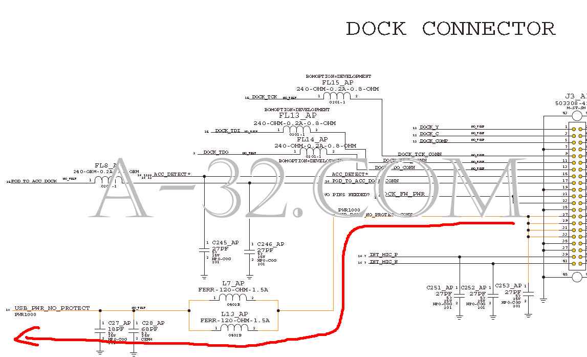 2) As a non-reverse (positive) voltage goes to Q4, current goes thru it because Mosfet Q4 is on all the time. The zener diode DZ6 limits the incoming voltage never goes above 8.2V. A sensor signal "USB_PWR_RPROT" is formed which is monitored by Power IC U18 Pin 17 "VBUS". "VBUS_OV" is a active low signal from U18 Pin 60 which controls Q5 to be turned on. If U18 senses that "VBUS" is an over voltage, U18 ouputs "VBUS_OV" high and Q5 will be turned off. U18 then is protected. The voltage "VBUS_PROT" can be measured at C190 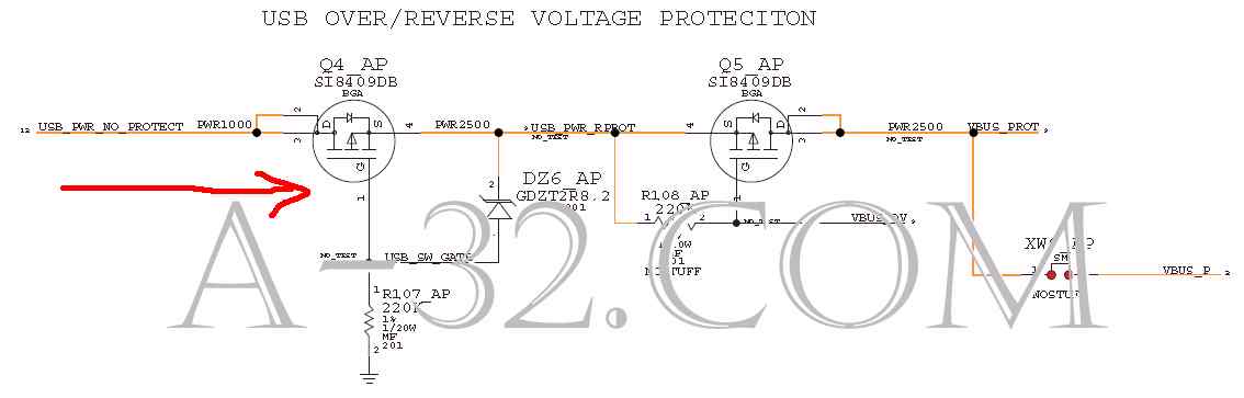 3) At this point, CPU controls U41 Pin 64, 65 "IBAT" or "BATT_VCC_CURSNS" to charge battery thru battery connector J7 Pin 4 if battery is low in voltage. 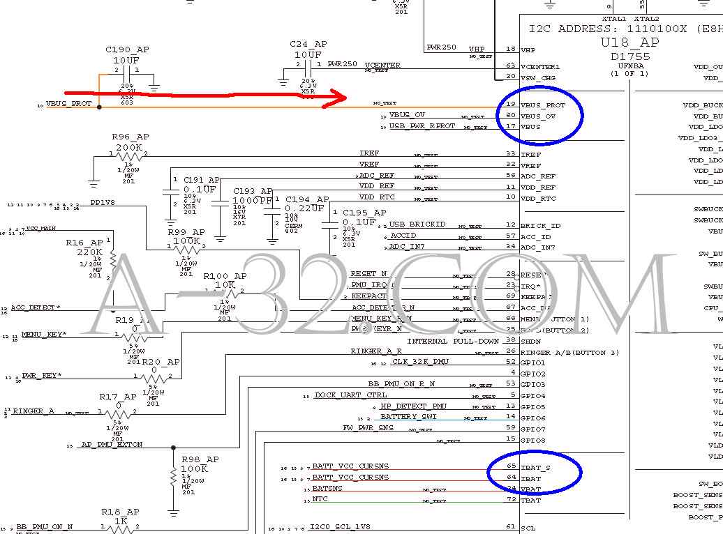 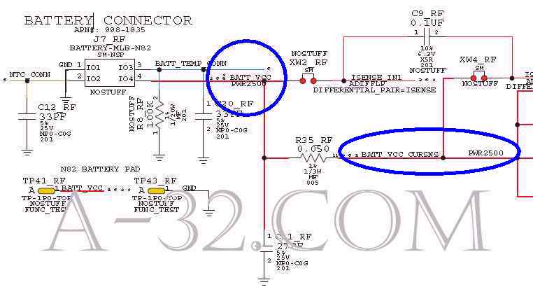 Source of all circuit diagram are from Apple's schematic. iPad, iPhone, iPod, Macbook are trademarks of Apple company. |