

|
|
|
|
Products & Services
|
iPhone 4 Power On Time SequenceU48 Power IC: 1) After a battery voltage of 3.8V inputs to U48 Pin J9, H7, L9, L10, U48 has the power to start a combined circuit of component Y1, PMU, C82, C83. This circuit generates a clock signal of 32.768 Khz at U48 Pin G1, H1. (1st time voltage input to U48) 2) U48 now outputs a standby voltage of 1.8V "PP1V8_ALWAYS" at Pin J1. One end of DZ11 has this voltage. 3) Press the Power button or short out DZ11 to trigger a digital signal 1.8V-0V-1.8V or "Pwr_key_L" or "Hold_key_L" at J7 Pin 6 which then goes to U48 Pin J8, an output voltage of 3.8V "VCC_MAIN" at U48 Pin L7 is generated. 4) "VCC_MAIN" inputs to a total of 9 pins on U48's VCC_MAIN module. They are A5, A7, A10, D11, H10, G10, K5, K3, K11. (2nd time voltage input to U48) 5) With the help of L17, C168, a voltage 1.8V "PP1V8_VBUCK2" is genetered at U48 Pin A4, and then inputs to U48 Pin F11 and B8. (3rd time voltage input to U48) 6) All voltages on U48 are ready includes Pin C11 "PP3V0_nand". U52 CPU: 1) U52 needs serveral voltages to start up. They are from U48 Power IC and U7 voltage regulator - PP1V8, PP1V2, PP1V1, PP3V0_IO, PP1V35, PP1V2_SDRAM. 2) A combined circuit of Y2, C7, C13, R40, R41 generates a clock signal of 24 Mhz at U52 Pin A12, B12. 3) With the help of voltage divider R17 and R24, a reset pulse of 3V which is originally generated by U48 Pin C7, 3V-0V-3V or "RESET_L" or "RESET_3V0_L" resets U52 at Pin B19. 4) 3 main components (Voltage, Clock and Reset) for CPU are ready. U52 starts to self POST and prepares to read programs in U1. U1 Memory: 1) U1 Pin N7, N1, M6, B6 is powered by a voltage of 3V "PP3V0_nand" which is from Power IC U48 Pin C11. After U52 POST done, U52 searches U1 for initial program. 2) U52 and U1 communicates each other thru control bus, address bus and data bus. Initial program instructs U52 to run up all other functions on the phone. 3) Now the iPhone 4 is turned on. WDOG and I2C: 1) U52 Pin F22 provides a Watch Dog voltage to U48 Pin B7 thru R93. This voltage keeps U48 running and maintains the steady output power. 2) U52 Pin AB6 and AB5 output clock "SCL" and data "SDA" signals (I2C) to U48 Pin B3 and C3. With I2C control from U52, U48 supplies power to all circuits on their own needs. 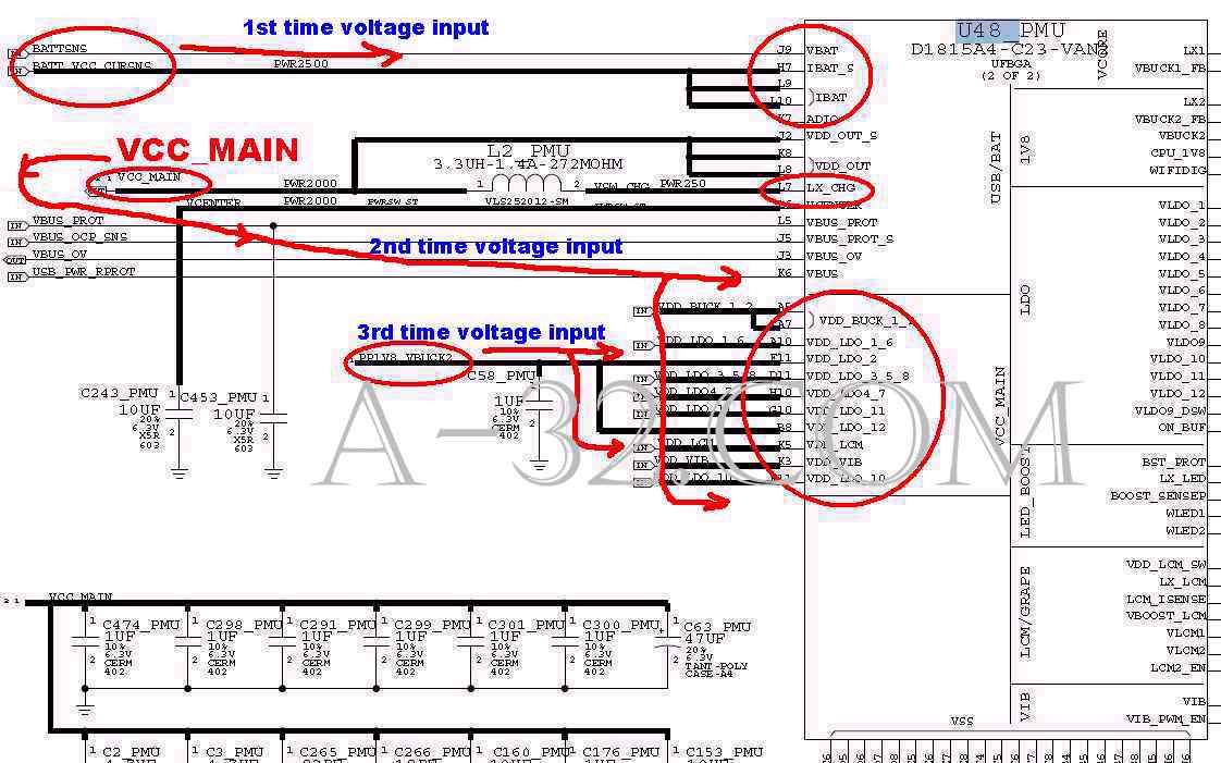 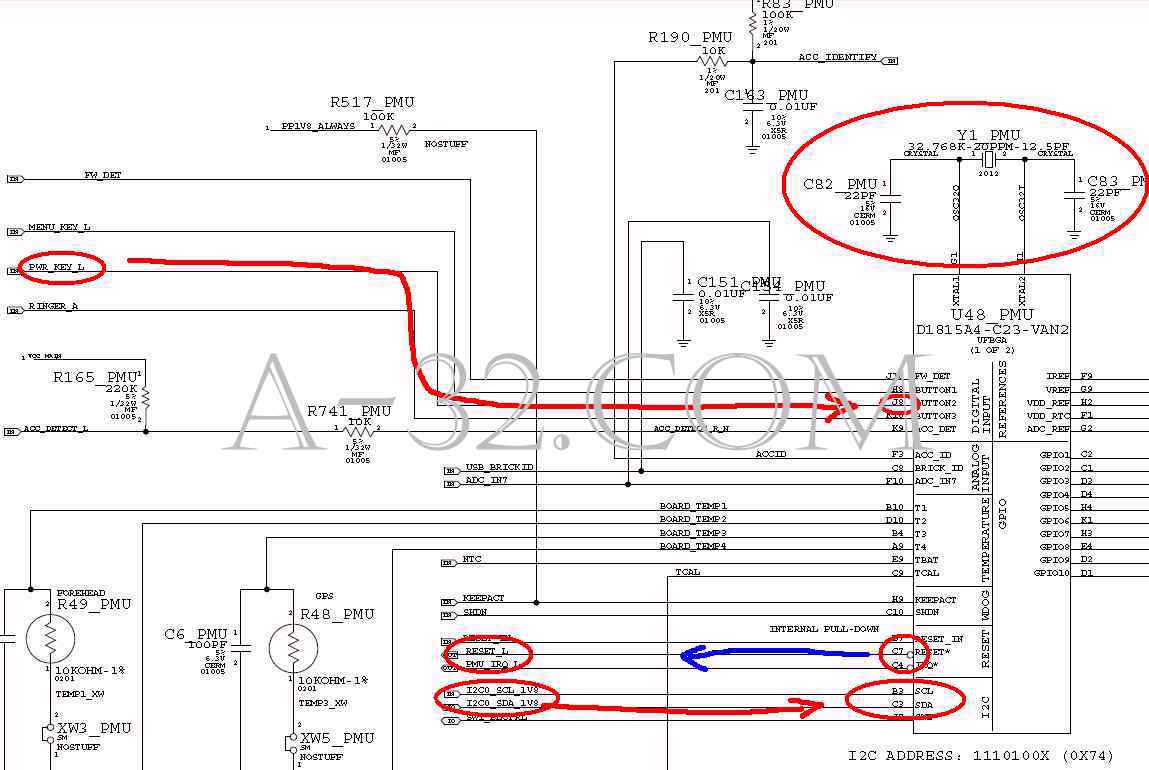 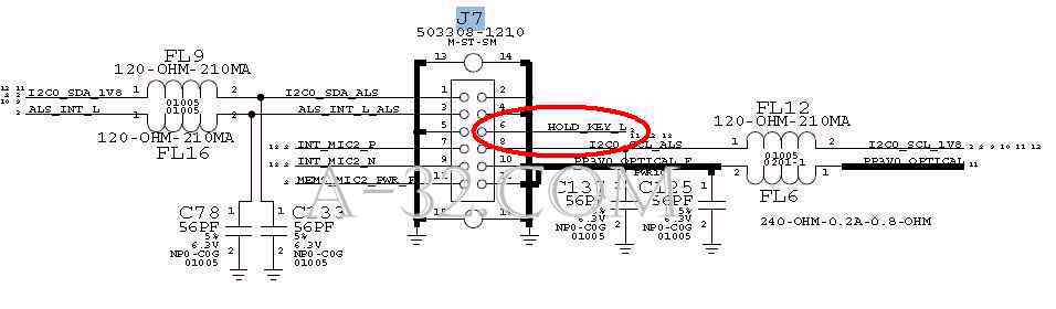 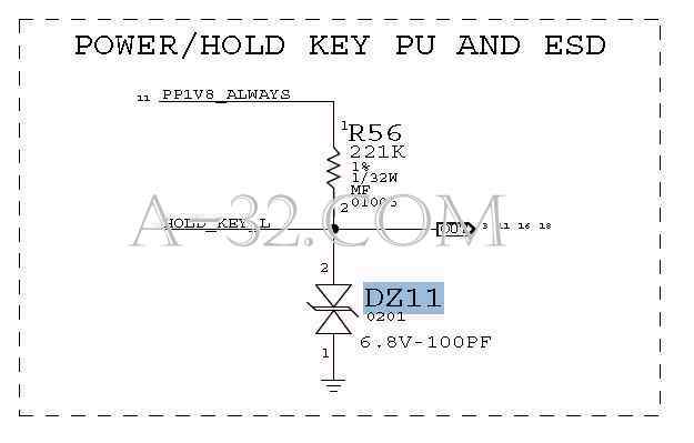 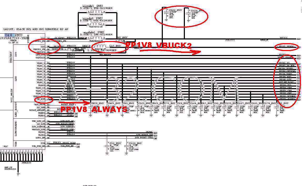 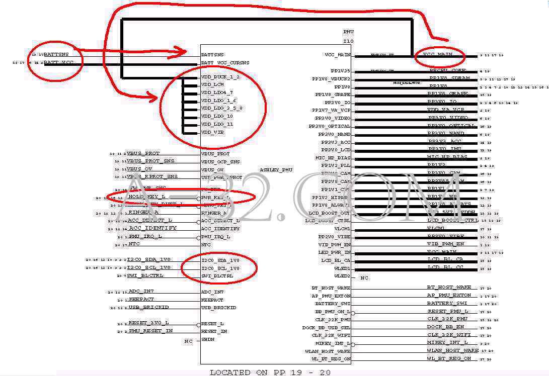 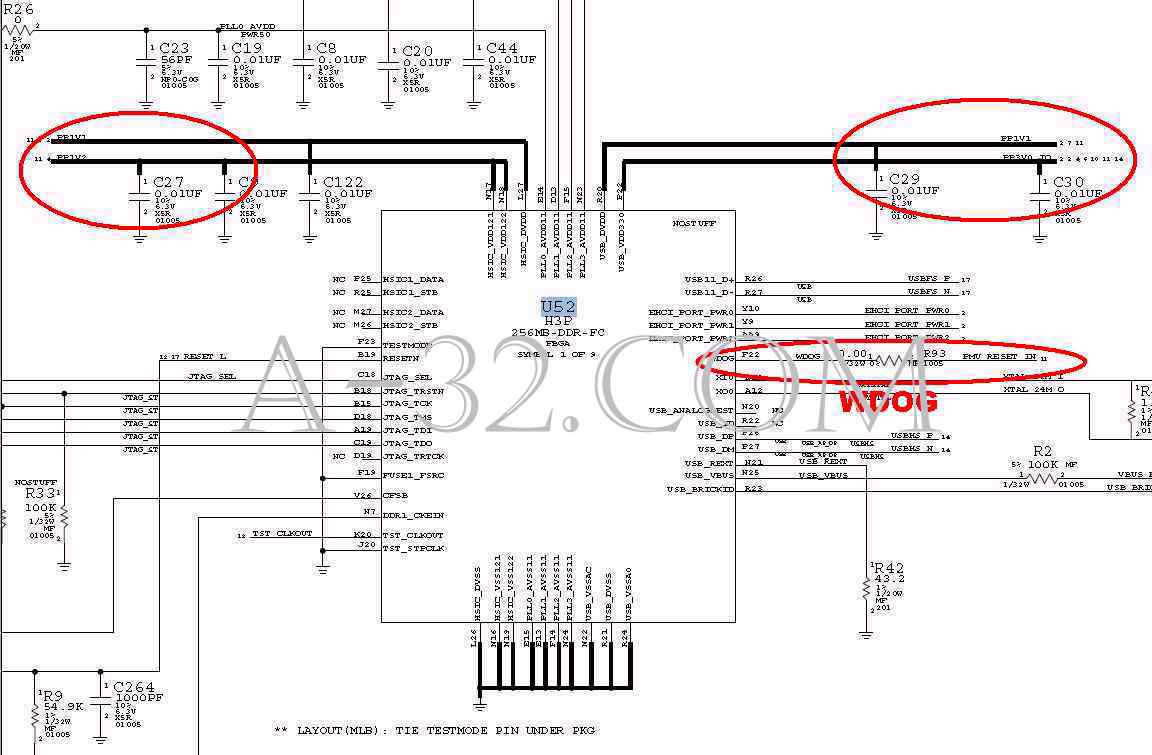 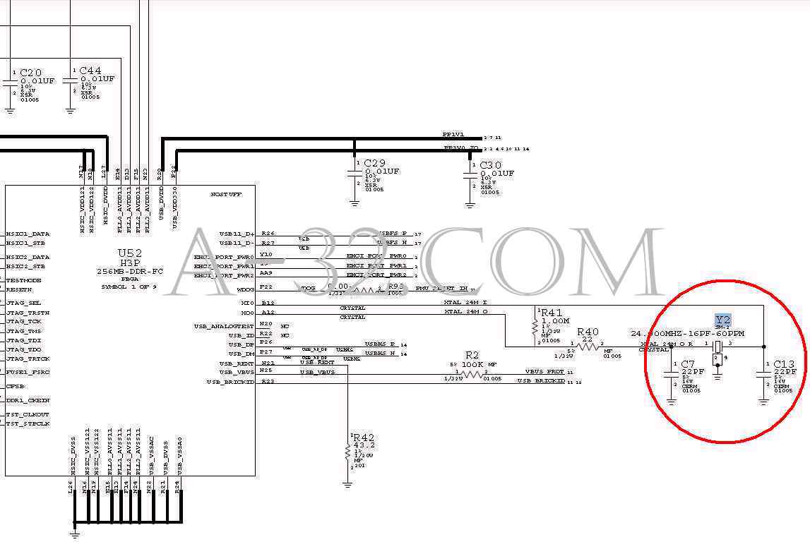 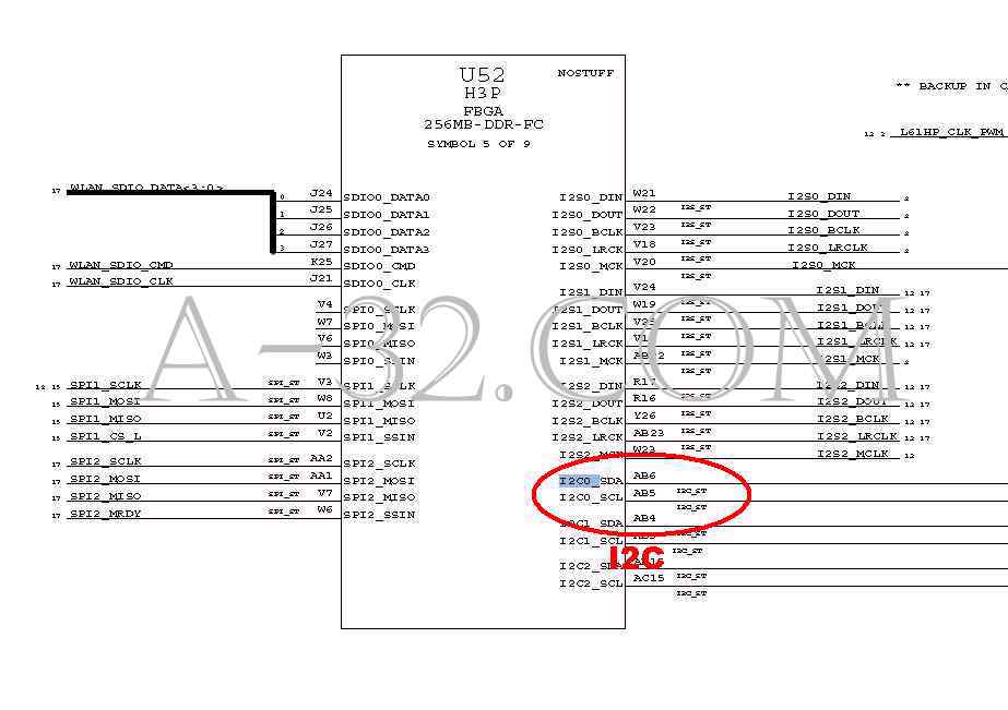 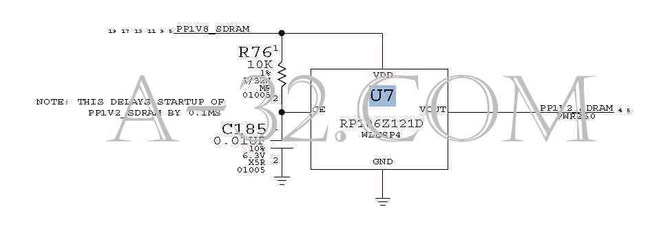 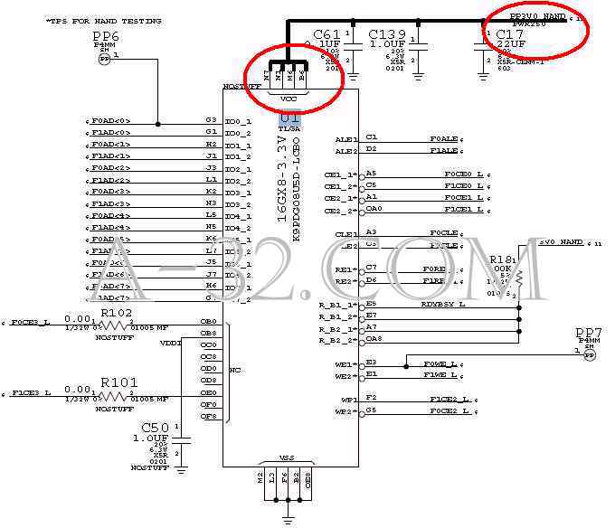 Source of all circuit diagram are from Apple's schematic. iPad, iPhone, iPod, Macbook are trademarks of Apple company. |