

|
|
|
|
Products & Services
|
iPhone 4 Over/Reverse Voltage Protection1) Sometime people accidentally put a wrong charger or a bad charger to charge their iPhone. It is apparently easy to damage the iPhone's circuit or the battery. In order to protect the iPhone, it is important that iPhone should have the ability to protect from the reverse and over voltage.Once iPhone charger is connected, a voltage of 5V "USB_PWR_NO_PROTECT" is from dock connector J3 Pin 12, 14, 16, 18. This voltage is filtered by a LC circuit of L3, L4, C67, C226 to eliminate the ripple. Q2 is a dual P channel MOSFET. It turns on if gate is low in voltage. Q2 (2 of 2) is always on in the schematics because its gate is ground all the time (thru R113). If a reverse (negative) voltage goes to Q2 (2 of 2), its body diode is reverse bias and stops the current flow it. This avoids the bad or wrong charger which is accidently pluged in the charging port. iPhone circuit is protected and safe. (Reverse voltage protection) 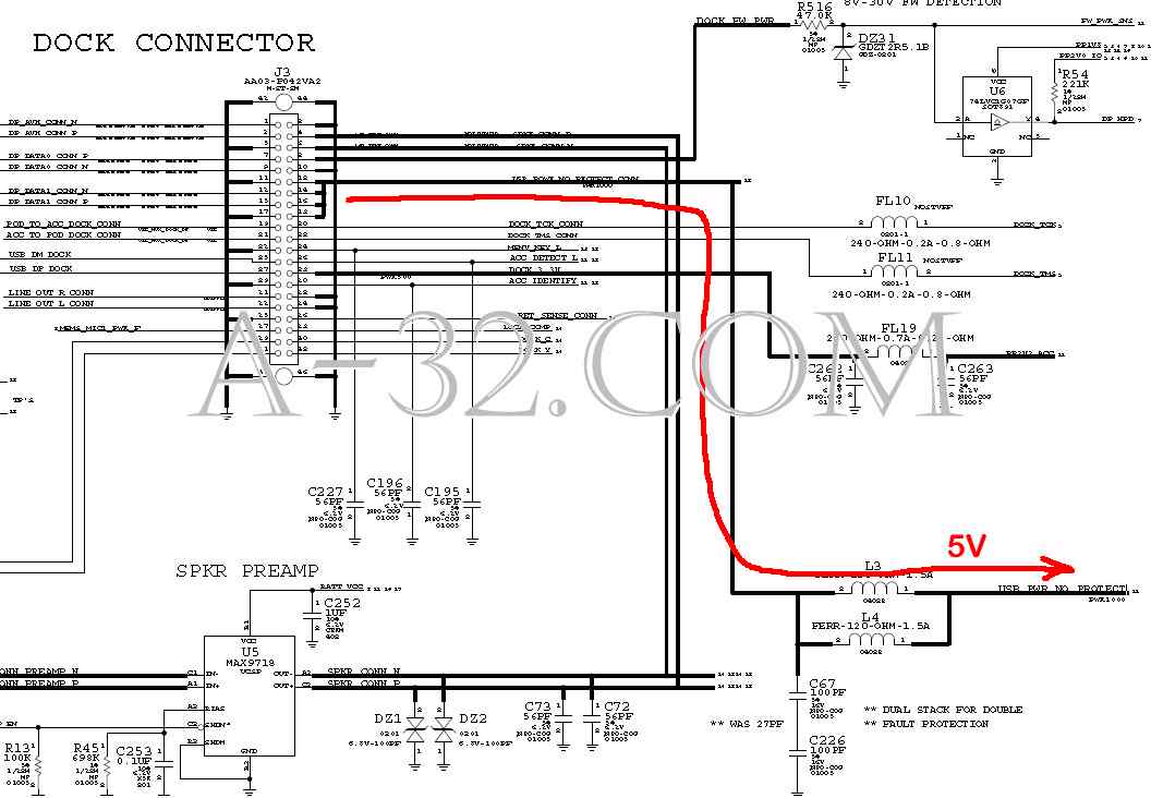 2) As a non-reverse (positive) voltage goes to Q2 (2 of 2), it passes thru Q2 from D1 to B1 because Q2 is always on due to G1 is ground thru R113. A sensor signal "VBUS_RPROT_SNS" or "USB_PWR_RPROT" (2V) is formed by a voltage divider DZ6 and R37. DZ6 is a 7.5V Zener diode so that input voltage will never go up to 7.5V. "VBUS_RPROT_SNS" is monitored by Power IC U48 Pin K6. "VBUS_OV" is a active low signal from U48 Pin J3 which controls Q3 to be turned off. If U48 senses that "VBUS_RPROT_SNS" not is present, it keeps "VBUS_OV" unchanged (low in signal level) and Q3 still off. Otherwise U48 ouputs "VBUS_OV" high and Q3 turns on. Gate G2 on Q2 (1 of 2) is ground and Q2 (1 of 2) turns on. Q2 Pin B2, C2, C3 have voltage of 5V "VBUS_PROT". This voltage can be measured at C453 (1st time voltage protection) 3) At this point, U48 Pin J5 will look at this protected voltage "VBUS_PROT_SNS" or "VBUS_OCP_SNS" thru R81 one more time to make sure that it is a voltage of 5V. If not, U48 outputs "VBUS_OV" low to the gate of MOSFET Q3 and Q3 turns off, ie Drain and soruce of Q3 is open circuit. Gate G2 on Q2 (1 of 2) is high and Q2 (1 of 2) turns off. U48 is out of the bad voltage. (2nd time voltage protection) 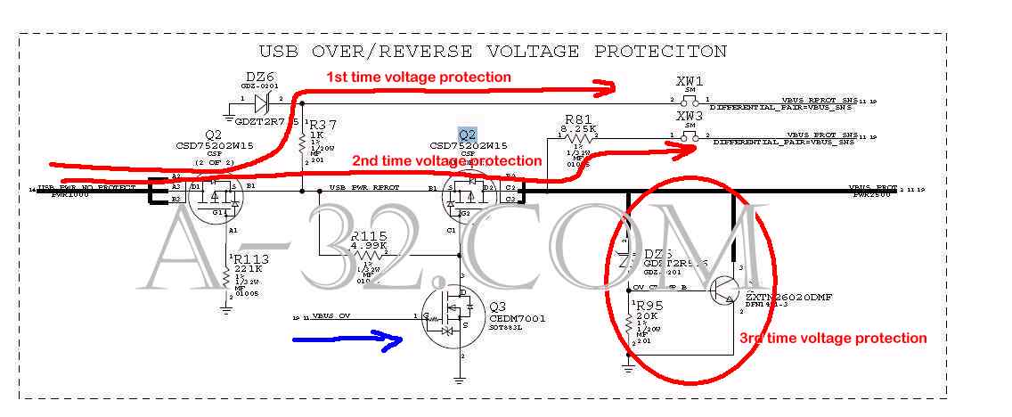 4) There is one more protection at the circuit of DZ5, R95, Q1. A voltage divider of Zener diode DZ5 and R95 is connected to Q1. It forms a transistor voltage regulator circuit and outputs a regulated voltage which is equal to base-emitter voltage of Q1 (Vbe) plus Zener voltage of DZ5 (5.6V). As "VBUS_PROT" goes up and Vbe of Q1 will increase. Whenever "VBUS_PROT" is large than 6.2V, Q1 turns on and "VBUS_PROT" will reset to 5.6V. U48 is once again away from the input of overvoltage. (3rd time voltage protection) 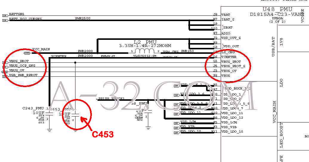  Source of all circuit diagram are from Apple's schematic. iPad, iPhone, iPod, Macbook are trademarks of Apple company. |